
A vessel may pass a basic strength check and still contain a flaw that changes the integrity decision. A vessel structural integrity assessment using a Failure Assessment Diagram (FAD) evaluates a defect against fracture and plastic-collapse limits, bringing crack size, material behaviour, geometry, and loading into one framework. The diagram shows whether the flaw falls within an acceptable assessment region or needs further evaluation.
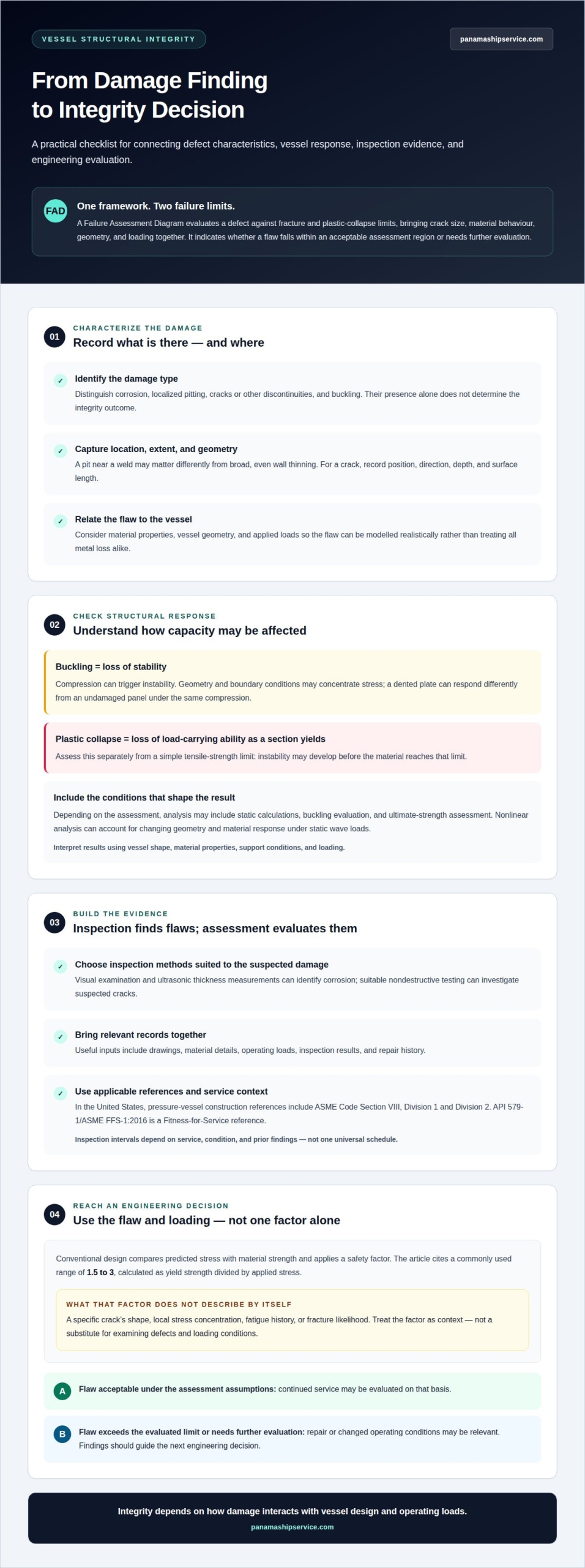
Corrosion, pitting, cracks, and buckling can all affect structural capacity, but their presence alone does not determine the outcome. The key question is how damage interacts with the vessel’s design and operating loads. A useful assessment considers these conditions together rather than relying on a single safety factor.
This article explains how FADs support integrity decisions, what conventional design factors can and cannot show, and how crack shape, corrosion, fatigue, and buckling affect the analysis. It also outlines how inspection findings and engineering data can clarify structural integrity and identify issues for further evaluation.
Key Takeaways
- Assess corrosion, pitting, discontinuities, and buckling by considering how each affects the vessel’s load-bearing capacity.
- Account for the depth and shape of semi-elliptical cracks when evaluating flaws in cylindrical sections.
- Use conventional safety factors as context, not as a substitute for examining specific defects and loading conditions.
- Learn how a Failure Assessment Diagram brings fracture and plastic-collapse considerations together to guide integrity decisions.
Corrosion, pitting, discontinuities, and buckling
A sound integrity decision considers both material loss and structural response. Corrosion, cracks, and instability can change how a vessel carries operating loads.
Corrosion, Pitting, and Discontinuities
Corrosion removes material, pitting creates localized cavities, and discontinuities include cracks or other breaks in structural continuity. A pit near a weld, for example, may matter differently from broad, even wall thinning because its location and shape affect local stress. Record the damage’s position, extent, and geometry, then relate those findings to material properties and applied loads. This allows engineers to model the flaw realistically instead of treating all metal loss alike.
Buckling and Structural Instability
Buckling is a loss of stability under compression, while plastic collapse occurs when a section can no longer carry its load as it yields. Instability can develop before the material reaches a simple tensile-strength limit, particularly where geometry or boundary conditions concentrate stress. For example, a dented plate may behave differently from an undamaged panel under the same compression. Assessing these mechanisms helps distinguish local deformation from a broader loss of load-carrying capacity.
Buckling and Ultimate Strength Assessment
Buckling and ultimate-strength assessments examine how a vessel responds as loads increase toward instability or collapse. The analysis may include static calculations, buckling evaluation, and ultimate-strength assessment. Nonlinear analysis can account for changes in geometry and material response under static wave loads. Engineers interpret the results using the vessel’s shape, material properties, support conditions, and loading. These checks help establish whether a damaged region remains structurally adequate under the conditions assessed.
Inspection and Assessment Planning
Inspection finds and characterizes damage; fitness-for-service analysis evaluates whether a specific flaw remains acceptable for continued operation. Visual examination and ultrasonic thickness measurements can identify corrosion, while suitable nondestructive testing, such as the solutions offered by internationaltestingservices.com, can investigate suspected cracks. In the United States, pressure-vessel construction references include ASME Code Section VIII, Division 1, and Division 2; API 579-1/ASME FFS-1:2016 provides a Fitness-for-Service reference. Applicable inspection intervals depend on service, condition, and prior findings, not one universal schedule.
Cost depends on scope, access, damage, and analysis requirements; a quote is provided on request. Timelines also depend on inspection access, data quality, and assessment complexity. Useful records include drawings, material details, operating loads, inspection results, and repair history. An unacceptable flaw can lead to repair, operating restrictions, or failure, so the findings should guide the next engineering decision.
Semi-elliptical cracks in cylindrical vessel sections
After an assessment, the choice between repair, rerating, or continued service depends on whether the measured flaw remains acceptable under the assessed loading. Repair addresses the defect; rerating changes operating conditions, while continued service relies on an acceptable evaluation.
Crack Geometry and Orientation
A semi-elliptical crack has a curved front and is defined by its surface length, depth, and orientation. In a cylindrical vessel section, a crack running along the vessel axis interacts differently with pressure loading from one crossing that axis. Record the crack’s position and direction, then establish its depth and surface length. These dimensions help engineers model the flaw and assess its effect on the vessel wall.
Stress, Fracture, and Crack Growth
Fracture mechanics relates crack geometry and material response to the stresses produced by operating loads. Repeated pressure cycles can drive fatigue growth, while a corrosive environment can contribute to corrosion fatigue or stress corrosion cracking. Those mechanisms differ, but each can extend a flaw over time. Crack-growth analysis uses the loading history and material behaviour to estimate how the crack may develop; the Paris equation’s exponent m is usually between 3 and 4.
Crack Acceptability and Fracture Mechanics
Fracture mechanics evaluates whether a crack’s dimensions and stress conditions remain within an acceptable limit. For one pressure-vessel case study, normal evaluations using API-579, BS-7910, and R6 found an acceptable critical crack length of 40.64 mm and depth of 10.16 mm. These are case-specific results, not universal thresholds. The evaluation connects flaw dimensions with material properties and loading to support a reasoned decision about continued service or repair.
Compare the detected flaw with its evaluated critical dimensions, then consider crack growth and operating loads. If the flaw is acceptable under the assessment assumptions, continued service may be evaluated on that basis. If it exceeds the evaluated limit, repair or changed operating conditions become relevant options.
Conventional design and safety factors
Conventional vessel design compares predicted stresses with material strength, then applies a safety factor. A commonly used factor ranges from 1.5 to 3, calculated as yield strength divided by applied stress. For example, a design with higher applied stress has less margin against yielding when material strength stays constant. This check gives engineers a structured baseline for evaluating a vessel’s ability to carry its intended loads.
That baseline has limits. A single factor does not describe a specific crack’s shape, local stress concentration, fatigue history, or fracture likelihood. Two vessel sections with the same nominal stress may behave differently if one contains a flaw or has local wall loss. Conventional calculations establish design margins, while defect-focused assessment examines how actual damage, material response, and loading interact. This distinction matters when inspection findings differ from the original design assumptions.
Design requirements also depend on equipment category and applicable construction rules. ASME Code Section VIII, Division 1, provides rules for pressure-vessel construction; ASME Code Section VIII, Division 2, provides an alternative set of pressure-vessel construction rules. For nuclear facility components, ASME Code Section III, Division 1, governs construction rules. BSI PD 5500, Fourth edition, is a specification for unfired fusion-welded pressure vessels. These named standards provide different frameworks, so the equipment’s design basis matters when interpreting calculations.
Use the original design basis as a reference: identify the material, geometry, design loads, and standard used. Then compare those assumptions with current inspection findings and operating conditions. If corrosion has reduced wall thickness, for example, the original stress calculation may no longer represent the vessel’s present condition. A safety factor alone cannot resolve this mismatch. It describes a margin, but an integrity conclusion must also account for actual geometry, material properties, defects, and service loads.
Failure Assessment Diagrams (FADs)
A Failure Assessment Diagram combines fracture and plastic-collapse considerations in one engineering assessment. Rather than treating a crack or excessive deformation in isolation, it relates the flaw’s fracture behaviour to the vessel’s ability to carry load. The assessment point is compared with a defined boundary to show whether the modeled flaw and loading remain within the diagram’s acceptance region.
R6:2015, Revision 4, is a cited procedure for assessing the integrity of structures containing defects. A FAD assessment uses calculated parameters to represent fracture and plastic collapse, then plots their interaction. This makes the method useful where a vessel contains a crack and engineers need to consider both failure modes together. The diagram does not replace sound inspection data: inaccurate crack dimensions or loading assumptions can shift the assessment point.
The reference-stress limit parameter is given as L = 0.5(1 + U / Y). This expression forms part of the assessment framework; it is not, by itself, a pass-or-fail result. Engineers must apply the relevant method consistently and interpret the calculated point against the applicable FAD boundary. For example, a crack under greater loading may produce a different assessment point than the same crack under lower loading.
In practice, the analysis connects four inputs: measured crack geometry, material behaviour, applied loading, and the selected assessment procedure. Engineers calculate the relevant parameters, plot the resulting point, and compare it with the diagram’s boundary. A point within the acceptable region means the modeled case meets that diagram criterion. A point outside it signals that the assessed conditions need further engineering attention, such as reviewing assumptions or considering changed operating conditions.
The key takeaway is that a FAD tests interacting failure mechanisms, not crack size alone. Use R6:2015, Revision 4, as the named assessment reference, and keep the inspection measurements and loading basis aligned with the model. That connection makes the diagram a decision tool, rather than a standalone graphic or substitute for engineering judgment.
Panama Ship Service: Mechanical Ship Repairs
When assessment findings call for repair, Panama Ship Service provides Mechanical Ship Repairs. Use the engineering results to identify the affected structure and define the repair scope. The FAD informs integrity decisions, but it does not replace repair planning.
For damage below the waterline, Panama Ship Service’s Underwater Hull Services address hull needs. Marine Surveys support vessel condition reviews, while Mechanical Ship Repairs address repair requirements. These services provide practical next steps when an assessment identifies work that needs attention, without treating every FAD result as an automatic repair instruction.
Match the next action to the finding: document the defect, determine whether repair or changed operating conditions are needed, and plan suitable work. Contact Panama Ship Service to discuss your vessel’s repair or hull-service requirements.
Turn the assessment into a clear next step
A useful vessel structural integrity assessment should lead to a defined operational decision, not remain an engineering report. Turn the findings into a practical scope: identify the work needed to address the vessel’s condition and the services that support its next operational phase. Keep the assessment’s assumptions and limitations visible as the plan develops.
When findings call for repair, Panama Ship Service offers Mechanical Ship Repairs and Underwater Hull Services. It also offers MARPOL Disposals. Match the next step to the work identified, so technical decisions address practical vessel requirements rather than becoming a generic maintenance plan.
If you’re ready to discuss the operational work identified by your assessment, contact Panama Ship Service. A clear next step helps your team move forward with greater confidence and a more focused plan.
Frequently Asked Questions
What is a vessel structural integrity assessment?
A vessel structural integrity assessment evaluates whether a vessel’s structure can perform safely under its operating conditions. It brings together inspection findings, design information, material properties, and expected loads to support decisions about condition and necessary action. For example, engineers can assess a recorded hull defect in light of its location and service loading, helping distinguish a maintenance concern from a flaw requiring further analysis.
What are the steps in a vessel structural integrity assessment?
The assessment typically moves from defining the scope to documenting a decision. First, identify the vessel area and operating conditions of concern. Next, gather relevant drawings, material records, inspection results, and service history. Then characterize the damage and carry out the engineering analysis suited to the issue. Finally, document assumptions, findings, and proposed actions. A clear record helps vessel teams connect technical conclusions with maintenance planning.
How are corrosion, fatigue, cracking, and other vessel damage evaluated?
Engineers evaluate damage by considering its type, location, extent, and effect on the structure under service conditions. For example, a fatigue crack near a repeatedly loaded connection calls for attention to its growth mechanism, while broad-area corrosion requires evaluating remaining material and load effects. Engineers interpret inspection observations alongside operating history and design information so the assessment addresses the specific damage, not just its appearance.